More Logic
In the previous unit we looked at AND,OR and NOT logic. Today let's take a look at XOR logic.
- AND - Both inputs must be ON for the output to be ON.
- OR - At least one input must be ON for the output to be ON.
- NOT - Inverts the input: ON becomes OFF and vice versa.
- XOR - Both inputs must be different for the output to be ON ie one or the other
- NAND - NOT AND (see below)
- NOR - NOT OR (see below)
Logic Gates
Logic gates are used to process 1 and 0.

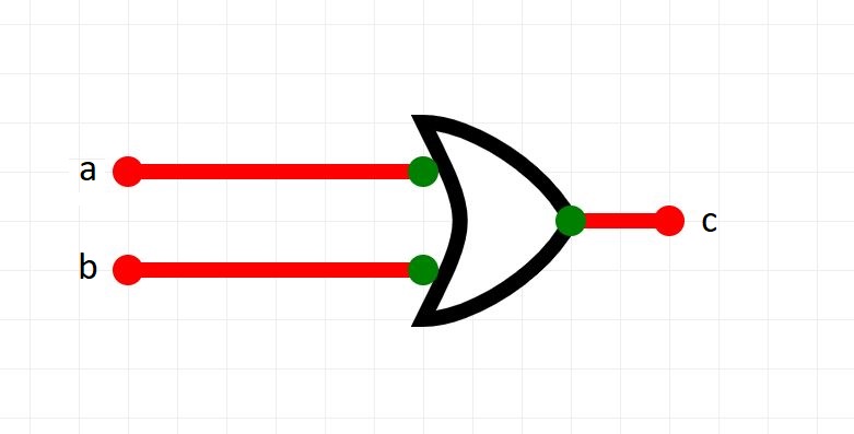


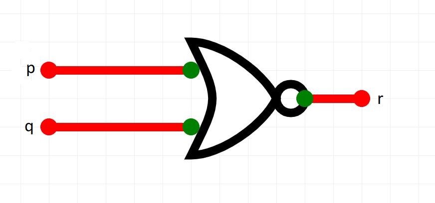
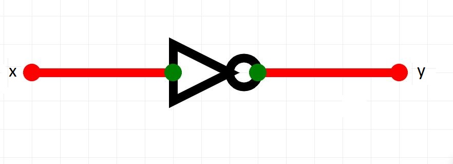
Click on each one to view its name.
Which one is the odd one out?
Real-World Connection: Smart Tools
A Woodcutting Company uses a digital sensor system to determine if a woodcutter is busy.
Note: Woodcutters are experts at using saws and axes.
A woodcutter is busy if:
- He is holding a saw but not an axe
- He is holding an axe but not a saw
Note: if he is holding both an axe and a saw, he is not busy because it is impossible to use both at the same time.
In this activity, you will design a smart woodcutter system using logic gates in , simulating how computers process sensor information.
Step 1 - Identify inputs
We will design a logic circuit which has 2 inputs:
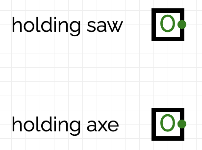
- is holding axe
- is holding saw
Each input will be either 1 meaning true or 0 meaning false.
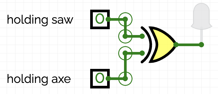
In CircuitVerse, place 2 inputs and annotate them as follows
Step 2 - identifying logic gates
A woodcutter is busy if:
- He is holding a saw but not an axe
- He is holding an axe but not a saw
In this case, he is busy if only one of the inputs is true, not both.
This is XOR logic.
To simulate a woodcutter being busy or not, we will use a lamp: when the lamp is ON, it means the woodcutter is busy.
Step 3
Does it work?
Test your design for each of the 4 input combinations.
- When the axe input is 0 and the saw input is 1, the woodcutter is busy.
- When the saw input is 0 and the axe input is 1, the woodcutter is busy.
- otherwise the woodcutter is not busy
Use the output to complete this table and check that it is correct.
| has axe | has saw | Busy |
|---|---|---|
| 0 | 0 | |
| 0 | 1 | |
| 1 | 0 | |
| 1 | 1 |
This is XOR logic and can be descibed as follows:
The output is 1 if either, but not both, of the inputs is 1.
Paste a screenshot of this table into the worksheet where indicated.
Step 4 - Extension
The system designers have decided that a woodcutter can never be busy if he is hungry. He needs to prioritise lunch.
So, a woodcutter is busy if:
A woodcutter is busy if:
- He is holding a saw but not an axe
- He is holding an axe but not a saw
AND
he is not hungry
Let's introduce a new input to our system, hungry.
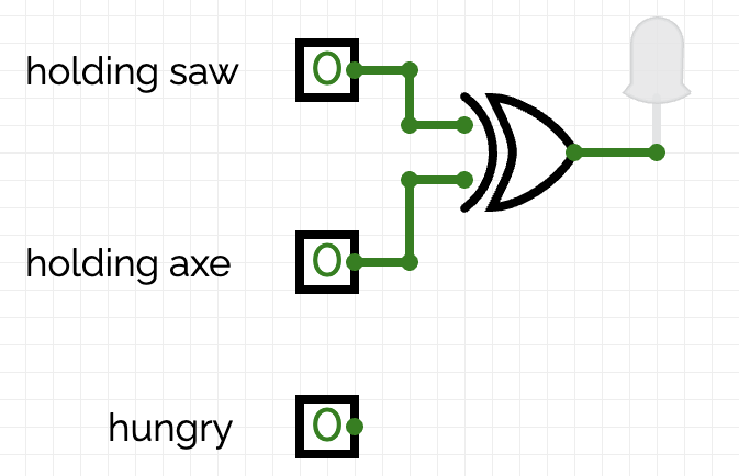
This is 1 when the woodcutter is hungry and 0 when he is not hungry.
Develop your circuit in CircuitVerse according to the above logic.
Step 5 - Truth Table
The circuit has 3 inputs.
And so there are 23 possible combinations.
In the worksheet, complete the Truth Table where indicated and predict what the output should be for each input combination.
Then, test your circuit by using the Truth Table. Does it work as expected?
Paste a screenshot of your circuit into the worksheet where indicated.
NAND and NOR
Can you remember the logic of an AND gate and an OR gate?
NAND is basically NOT AND
NOR is simply NOT OR
As so, if we can recall the truth tables for AND and OR, we should be able to derive the truth tables for NAND and NOR!
NAND Logic
| A | B | Output |
|---|---|---|
| 0 | 0 | 1 |
| 0 | 1 | 1 |
| 1 | 0 | 1 |
| 1 | 1 | 0 |
NOR Logic
| A | B | Output |
|---|---|---|
| 0 | 0 | 1 |
| 0 | 1 | 0 |
| 1 | 0 | 0 |
| 1 | 1 | 0 |
images courtesy of circuitverse