Introduction to Logic Gates
Introduction to Logic Gates and Circuits
Computers and digital systems process information using binary logic, where everything is represented by only two states: 1 (ON) and 0 (OFF).
These two-state systems are the foundation of modern electronics, from smartphones to security systems.
But how are these binary digits processed? The answer is:
logic gates
Logic Gates
Logic gates are used to process binary digits, 1 and 0. They allow computers to perform calculations and logical operations.
The following images are commonly used to represent common logic gates.

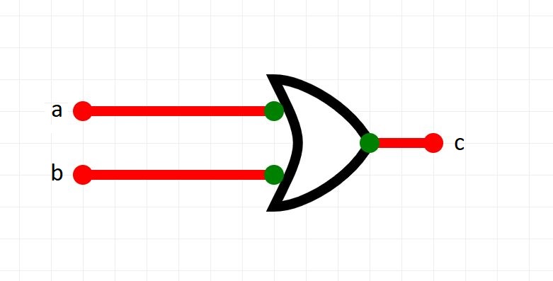


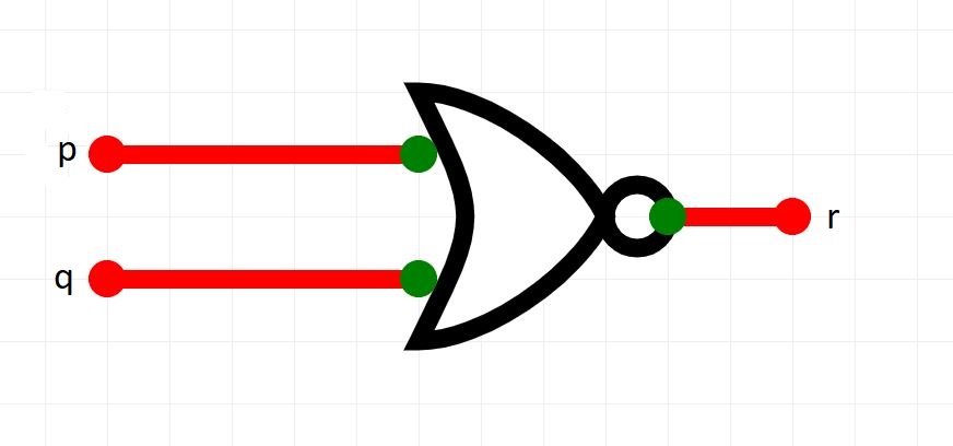
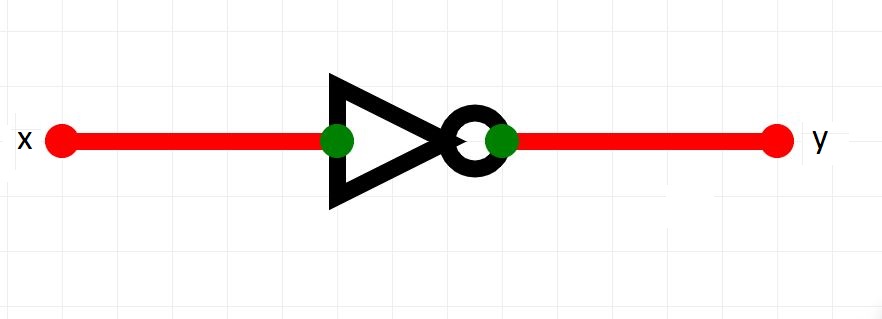
Click on each one to view its name.
Which one is the odd one out?
Part 1 - Circuit Verse
We are going to use a tool called to help us explore logic gates and logic circuits.
Watch the video and complete Part 1 of the worksheet.
Part 2 - Real-World Connection: Smart Systems
Think about a smart security system. The door should only unlock if certain conditions are met, such as:
A valid keycard is scanned OR the correct security code is entered
AND
It is during business hours
Step 1 - Identify inputs
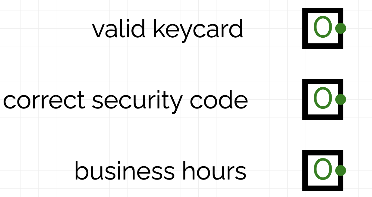
This problem has 3 inputs:
- has a valid keycard
- enters correct security code
- is during business hours
Each input will be either 1 meaning true or 0 meaning false.
In CircuitVerse, place 3 inputs and annotate them as follows
Step 2 - identifying logic gates
The door will only unlock if :
A valid keycard is scanned OR the correct security code is entered
AND
It is during business hours
Let's consider the top half of this logical expression.
We will need 2 inputs to connect to an OR gate.
Also, to simulate the door opening, we will use a lamp: when the lamp is ON, it means the door is OPEN.
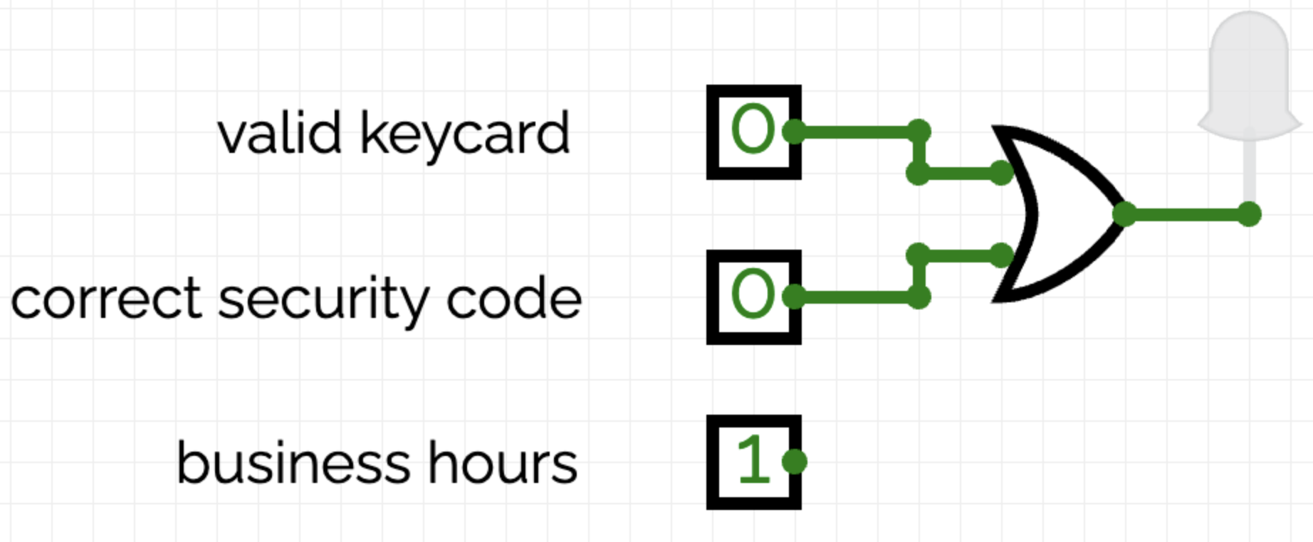
OR Logic tells us that if at least one of the inputs is 1, the output will be 1.
Does your circuit work as expected?
Step 3
Let's complete the logical design of this circuit.
Remember, the door will open if:
A valid keycard is scanned OR the correct security code is entered
AND
It is during business hours
So we need to connect the output of the top half of the expression to the bottom half using an AND gate.
Continue the design of the circuit in CircuitVerse as follows:

This is AND logic and can be descibed as follows:
The output is 1 only if both of the inputs is 1.
Step 4
Complete Part 2 of the Worksheet.
Part 3 - Adaptation
Other logic is used for late-night delivery staff.
A valid keycard is scanned OR the correct security code is entered
AND
It is NOT during business hours
That's right. Delivery staff also need a keycard or a code, but cannot enter during business hours.
Using exactly the same inputs as before, redesign the circuit for this scenario
Paste a screenshot of your circuit in the Worksheet where indicated.
Truth Tables
The tables that you filled in during this exercise are called Truth Tables.
Truth Tables are used by circuit designers to predict the correct output of a circuit for given inputs.
Then, when the circuit is actually developed, the truth table is used to check that the input/output combinations are correct.
images courtesy of circuitverse