
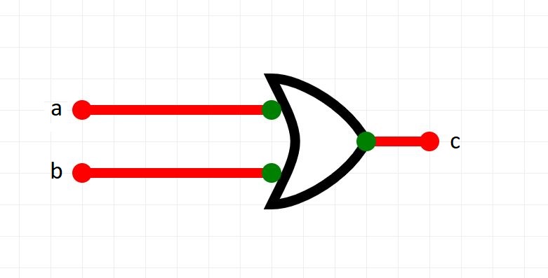


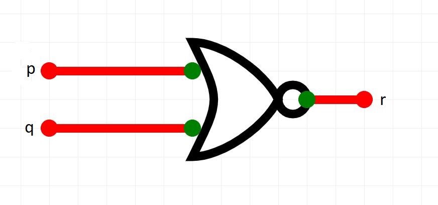
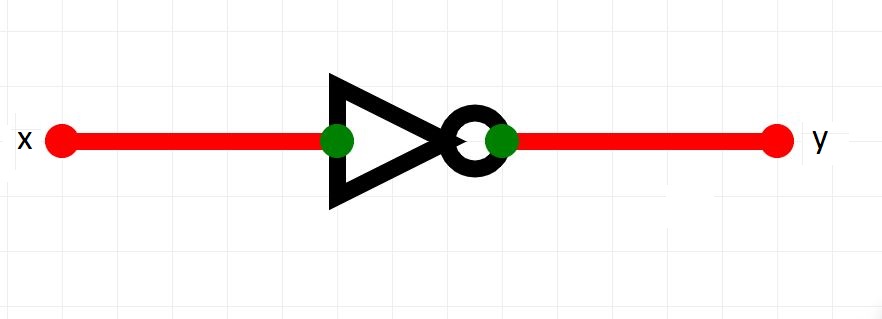
Click on each one to view its truth table.
So, different logic gates have different outputs depending on the inputs.
But what about circuits?
For example, consider the following logical expression:
I am happy if:
I am with friends AND it is NOT a weekday
OR
I am with friends AND we are eating
This expression has 3 inputs
So, we could reduce this as a logical expression to:
I am happy if:
f AND NOT w
OR
f AND e
which can be expressed as:
I am happy if (f AND NOT w) OR (f AND e)
What would a logic circuit look like to help us visualize the logic of this expression?
How can we accurately build a truth table for this kind of circuit. It has 3 or more gates and things can get complicated.
Let's follow a strategy to break up the problem.
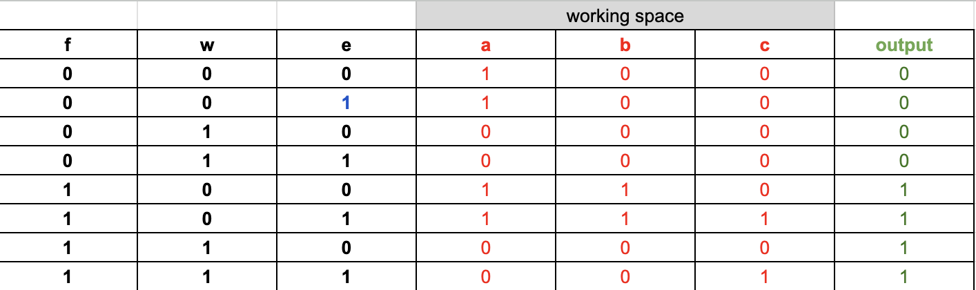
Draw a table and identify the inputs and outputs and all of the different combinations of input:
hint leave a gap in the middle of your work area. We can use this as you will see.
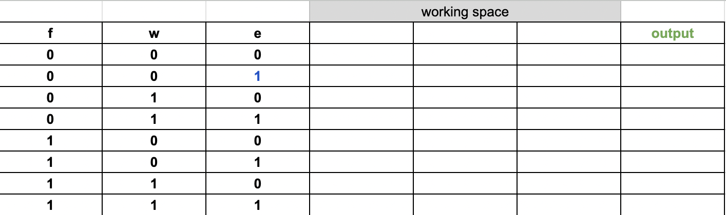
make sure all the input combinations are in sequence, from 000 to 111
Annotate the circuit so that there is a letter on each line in the circuit. Here we use a, band c.

Now determine the output at each of the letters in the circuit:

Now determine the final output. Looking at the above circuit we can see that the output is b OR c.
We know the values of b and c so we can determine the final output of the circuit.
Confirm your solution by building the circuit in circuitverse and checking your answer!
The truth table in this sample was drawn using MS Excel. You can use whatever you like to draw your Truth Tables eg pencil and paper etc.
Submit your worksheet as instructed.
