
Hardware and software
Truth Tables
So, different logic gates have different outputs depending on the inputs.
Here is a summary of the logic gates' inputs and outputs from the previous unit page:
NOT
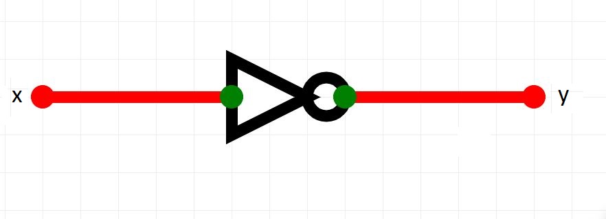
| x | y |
|---|---|
| 0 | 1 |
| 1 | 0 |
XOR / EXOR

| a | b | c |
|---|---|---|
| 0 | 0 | 0 |
| 0 | 1 | 1 |
| 1 | 0 | 1 |
| 1 | 1 | 0 |
OR
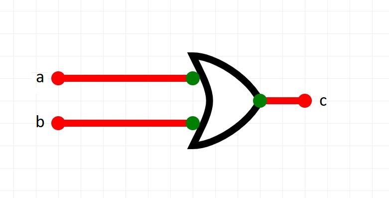
| a | b | c |
|---|---|---|
| 0 | 0 | 0 |
| 0 | 1 | 1 |
| 1 | 0 | 1 |
| 1 | 1 | 1 |
NOR

| a | b | c |
|---|---|---|
| 0 | 0 | 1 |
| 0 | 1 | 0 |
| 1 | 0 | 0 |
| 1 | 1 | 0 |
AND
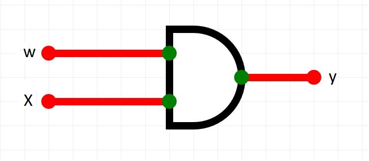
| a | b | c |
|---|---|---|
| 0 | 0 | 0 |
| 0 | 1 | 0 |
| 1 | 0 | 0 |
| 1 | 1 | 1 |
NAND
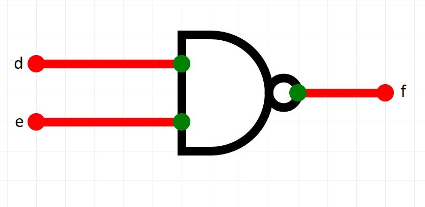
| a | b | c |
|---|---|---|
| 0 | 0 | 1 |
| 0 | 1 | 1 |
| 1 | 0 | 1 |
| 1 | 1 | 0 |
CIRCUITS
But what about circuits?
When we design an electronic logic circuit, we should create a TRUTH TABLE to show every expected output for every combination of inputs.
Then, when we build and test the circuit, we can check if it works as expected.
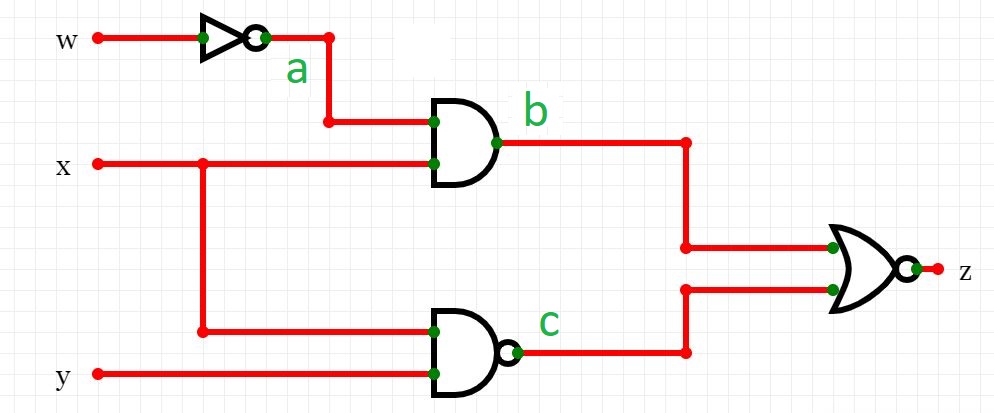
For example, how can we create a truth table for this circuit?

STEP 1
Draw a table and identify the inputs and outputs and all of the different combinations of input:
hint leave a gap in the middle of your work area. We can use this as you will see.

STEP 2
Annotate the circuit so that there is a letter on each line in the circuit. Here we use a, band c.
STEP 3
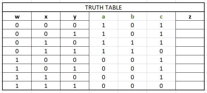
Now determine the output at each of the letters in the circuit:
STEP 4
Now determine the final output. Looking at the above circuit we can see that the output is b NOR c. We have the values for b and c so we can determine the final output of the circuit.

STEP 5
Confirm your solution by building the circuit in circuitverse and checking your answer!
Note
The truth table in this sample was drawn using MS Excel. You can use whatever you like to draw your Truth Tables eg pencil and paper etc.