Logic circuits
Scenario A
A lamp is controlled by two switches, Switch A and Switch B.
When Switch A is ON and Switch B is ON, the lamp turns on.
Flick the switches and see if the circuit works as intended.
Logic Gates
Digital circuits use logic gates to process inputs and determine outputs of a circuit.
The above circuit has 2 inputs. We can say that when A is ON, A = 1; when A is OFF, A=0 etc.
Because there are 2 inputs, there are 22 possible combinations of input.
For each combination, enter the output and check your answer. Use the simulator to help if you need it.
| A | B | Output |
|---|---|---|
| 0 | 0 | |
| 0 | 1 | |
| 1 | 0 | |
| 1 | 1 |
A Logical Expression
We can describe this logic with a logical expression:
output is 1 if A=1 AND B=1
This is AND logic and the logic circle in the above simulation represents an AND gate!
Scenario B
A different logic gate has been chosen to control the lamp.
Flick the switches and see if you can complete the following truth table.
| A | B | Output |
|---|---|---|
| 0 | 0 | |
| 0 | 1 | |
| 1 | 0 | |
| 1 | 1 |
A Logical Expression
What do you think the logical expression is this time?
Scenario C
A different logic gate has been chosen to control the lamp.
Flick the switches and see if you can complete the following truth table.
| A | B | Output |
|---|---|---|
| 0 | 0 | |
| 0 | 1 | |
| 1 | 0 | |
| 1 | 1 |
A Logical Expression
The logic gate that is controlling this circuit is called an XOR gate. Can you complete the logic expression:
output = 1 if ....
Logic Gates
Logic gates are used to process 1 and 0. The following logic gates all have 2 inputs:
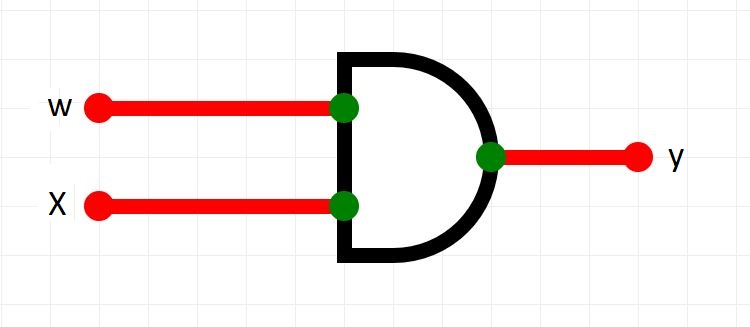
AND GATE
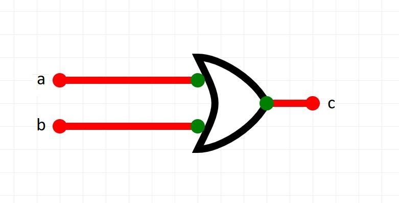
OR GATE

XOR GATE
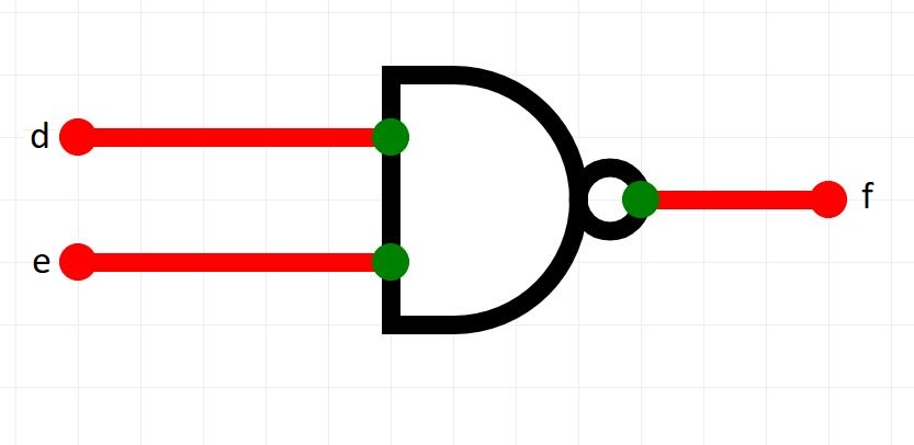
NAND GATE

NOR GATE
Click on each one to view its truth table.
Notice how we can deduce NOR and NAND logic if we are familiar with OR and AND logic.
Note: you do not have to remember the shapes of the gates in this course. We will use circles with the name of the gate inside.
The NOT Gate
A NOT gate has only 1 input. The output is simply the reverse of the input.
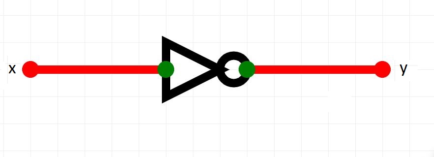
NOT Gate Truth Table
| x | y |
|---|---|
| 0 | 1 |
| 1 | 0 |
Answer these questions in your Google Doc.
- To get a 1 from an AND gate, what must all inputs be?
- To get a 1 from an OR gate, we need at least one kind of input. What is it?
- How can we get a 1 out of an EXOR gate?
- What is the purpose of a NOT gate?
- Compare the AND gate Truth Table with the NAND gate Truth Table. What do you notice?
images courtesy of circuitverse